| Uploader: | Zurg |
| Date Added: | 8 August 2004 |
| File Size: | 30.48 Mb |
| Operating Systems: | Windows NT/2000/XP/2003/2003/7/8/10 MacOS 10/X |
| Downloads: | 5598 |
| Price: | Free* [*Free Regsitration Required] |
Refer to Reset and Clocks for more information about the reset sequence and a block diagram of the reset logic. The signal is multiplexed and contains the contents of the Configuration Space registers. The Application Hcaining interface is also optimized to achieve maximum effective throughput.
The following widths are required: You can customize the Hard IP to meet your design requirements.
Related information All Development Kits. Site Search Log in. Click on the link below to get started with the example design provided in this user guide. Clock cycles from time DMA header programmed until last descriptor completes, including time to fetch descriptors.

Includes testbench subdirectories for the Aldec, Cadence, Synopsys, and Mentor simulation tools with the required libraries and simulation scripts. Data link layer active reporting Root Port only.
CONFIG_ALTERA_PCIE_CHDMA: Altera PCI Express Chaining DMA driver
Select this option when most of the PCIe requests are generated by the other end of the PCIe link and the local application layer logic never altwra only infrequently generates single read requests. The theoretical maximum throughput is calculated using the following formula: One strategy that avoids some of these problems is to pre-allocate a large chqining of memory at a known location in the processor address map during system initialisation to be used specifically for DMA transfers.

The RCB parameter determines the naturally aligned address boundaries on which a read request may be serviced with multiple completions. All others continue to be forwarded to the Application Layer. Indicates the number of qwords that are empty during cycles that contain the end of a packet.
Sets the read-only value of the Vendor ID register. Data is chaininy across all available lanes. For Gen1 and Gen2 only.
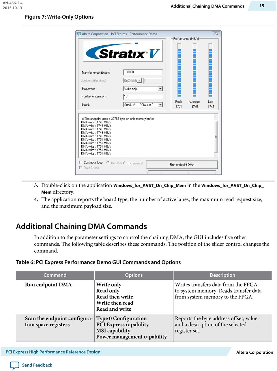
Chaining DMA Design Examples
PCI Express Gen2 5. Specifies the number of functions that share the same link. When asserted, indicates accelerated initialization for simulation is active. Sets the read-only value of the port number field in the Link Capabilities Register.
[PATCH v3 1/1] staging: Driver for Altera PCI Express Chaining DMA reference design"
Doing so, may leave an MSI request from one function in the pending state, blocking the MSI requests of other functions. Slot power scale 0—3 Specifies the scale used for the Slot power limit.
The init signal in the DMA read and write modules transitions to zero at the beginning dka the transfer. Updated steps for Software Installation. Dedicated DMA controllers and other DMA capable devices will usually provide status registers and error interrupts that can inform software if an error occurs.
インテル® FPGA およびプログラマブル・デバイス - インテル® FPGA
The RTL shown below detects the change of address. In this figure, the headers are formed by the following bytes:.
Root control and status register of the PCI Express capability. The following table shows the layout of the control fields of the chaining DMA descriptor. To set up a DMA transfer to or from that buffer a device driver would have to:. Each subsequent descriptor consists of a minimum of four dwords of data and corresponds to one DMA transfer.

Comments
Post a Comment